Understanding Phase Error in Fatigue and Dynamic Testing
Why Microseconds Can Distort Material Performance
Imagine you’re designing the next record-breaking running shoe or a silent electric vehicle. You’ve run the tests, and the data looks perfect. But there’s a hidden flaw: a timing error so small — less than the blink of an eye — that it renders your results useless. In high-frequency materials testing, this is the “silent saboteur” known as phase misalignment.
To understand why this matters, let’s look at how it impacts the world around us.
Real-Life Impact: When Microseconds Matter
Phase alignment isn’t just for lab scientists; it’s the difference between a high-performing product and a field failure.
- Electric Vehicle (EV) Comfort: EVs are incredibly quiet, making any hum or rattle a major problem. Motor mounts are tested at high frequencies to ensure they absorb vibrations. If the testing machine has a tiny phase lag, engineers might miscalculate the damping ability (tan delta), leading to a “noisy” cabin that frustrates drivers.
- The “Bounce” in Your Step: High-performance running shoes use “bouncy” foams that store and return energy. Testing these at the speed of a runner’s stride requires perfect phase alignment to measure energy loss. Even a 1o error can make a responsive foam look “dead,” potentially causing a brand to scrap a winning design.

- Smartphone Durability: The adhesives holding your phone screen together are cycled thousands of times to simulate years of pocket-flexing. Accurate phase measurement ensures the screen doesn’t delaminate over time; errors here lead to “ghost-touch” failures and expensive recalls.
- Aerospace Safety: Airplane wings undergo high-frequency “flutter.” Because aerospace parts are so rigid, their material phase angle is tiny. A small timing bias in the test can dominate the results, making a safe part look like it’s failing prematurely.
Why High Frequency Makes Everything Harder
Phase is fundamentally a measurement of time. At low frequency, phase errors are forgiving.
At high frequency:
- Inertial forces scale with acceleration
- Acceleration scales with frequency squared
- Microsecond delays translate into measurable phase shifts
| Frequency | 1° Equivalent Time Skew |
|---|---|
| 10 Hz | 277.8 µsec |
| 100 Hz | 27.8 µsec |
| 1000 Hz | 2.78 µsec |
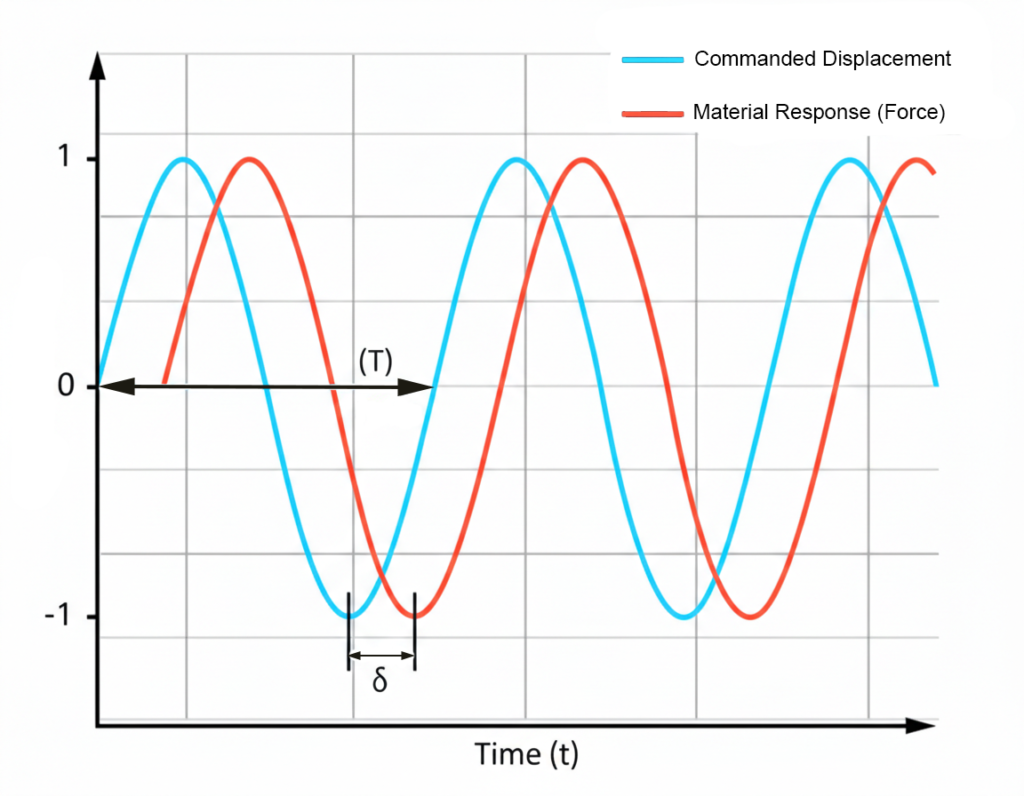
This “skew” comes from a combination of factors known as the distributed delay budget:
- Inertial Forces: The weight of the grips moving at high speeds creates “fake” force readings that are not actually experienced by the specimen.
- Signal Chain Delays: Filters used to clean up data (like anti-aliasing filters) add group delay, pushing the signals out of sync.
- Machine Resonances: Vibrations in the test frame can corrupt displacement readings, especially when measured far from the specimen.
The faster you test, the more precise your timing must be.
And once you move above a few hundred Hertz, control engineering and signal synchronization become as important as mechanical design.
Strategies for Correction: Main Compensation Methods
Engineers use a variety of “layers” to correct these errors, ranging from real-time hardware adjustments to post-test mathematical fixes.
Real-Time Methods
These methods adjust the machine while it is running to ensure the specimen feels the correct waveform.
- Amplitude/Phase Control (APC): This detects lag in the feedback and automatically adjusts the command signal’s phase and amplitude to compensate. It is highly effective for single-tone sine waves used in DMA.
- Adaptive Inverse Control (AIC): The system identifies the machine’s frequency response and “pre-distorts” the command to ensure the output is flat and synchronized.
- Inertial Compensation: In dynamic testing, the load cell does not measure only specimen force.
It measures:
Fmeasured = Fspecimen + m · a
Where:
m = mass of grips and moving components
a = acceleration
Acceleration increases with frequency:
a = (2πf)2 · x
Thus inertial force grows with f 2 .
At high frequency, inertial force can introduce:
- Amplitude error
- Phase error (because acceleration leads displacement by 90°)
This artificial component shifts measured phase between force and displacement.
So an accelerometer is mounted to the load axis to measure the movement of the grips. This signal is subtracted from the load cell reading to obtain the “true” force on the specimen.
Offline (Data) Methods
These are applied after the test to clean up the recorded data for accurate reporting.
- Cross-Correlation Alignment: This chooses a time shift that maximizes the correlation between force and displacement, making it a robust way to estimate fixed delays.
- Fourier/Sine-Fit Extraction: This method fits a fundamental sine wave to the data to extract phase, which is standard for DMA but can be biased by non-linearities.
- Frequency-Domain Correction: Engineers measure the system’s transfer function and subtract the known phase lag from the results across the entire frequency range.
How the Industry Fights Back
Different manufacturers use specialized layers of defense to keep data aligned:
- Instron: Uses Dynacell to subtract inertial forces using an accelerometer and WaveMatrix3 software to automatically detect and correct phase lag so recorded cycles are correctly in-phase.
- MTS: Emphasizes “servo-physics aware” control like Amplitude/Phase Control (APC) to adjust the machine’s command in real-time and Adaptive Inverse Control (AIC) to improve waveform reproduction.
- ZwickRoell: Focuses on high-speed hardware like EtherCAT for microsecond-level synchronization and mounting travel sensors coaxial and near the specimen to avoid frame-resonance artifacts.
Master the Phase with TACTUN
In the high-stakes world of dynamic characterization, TACTUN provides the tools to manage this “delay budget” with precision:
- Synchronous Timing Architecture: TACTUN ensures a common time base across all channels, eliminating the “fake phase” artifacts that occur when force and displacement are recorded on independent clocks.
- Advanced Filter Management: TACTUN allows for the documentation and control of every filter in the chain, preventing nonlinear group delays and channel-to-channel mismatch from biasing your results.
- Real-Time Compensation Integration: By supporting strategies like real-time phase compensation and inertial subtraction, TACTUN ensures that what you measure is what the specimen actually feels.
Share this post: